Welcome to Project APM.
Hello there! This webpage is meant to document our progress on interfacing and using the Arduino Pilot Mega V2.5 with the Raspberry Pi. Before you attempt to try out the steps listed below, please take some time to study and practice Python as well as C++ programming since we will be needing it.
Table of Contents:
1.)=========Introduction============
1.0--------The Underwater Robot Project
1.1--------The Competition
1.2--------Research
1.3--------Testing an ROV
2.)==============Setup==============
2.0--------Setting up the Raspberry Pi
2.1--------Your First Code
2.2--------GitHub
2.3--------Blinking LEDs
2.4--------I2C, SPI
2.5--------Using a Wireless Network Adapter
2.6--------Customising your Pi
3.)===========Interfacing===========
3.0--------Via USB
3.1--------Testing Connection
3.2--------Compass Sensor Readings
3.3--------The Finale~
4.)============Testing=============
4.0--------Testing the Program
4.1--------Pool Testing
[1.0] The Underwater Robot Project
Project APM is a subset of the Under Water Robot Project. The main project is to [re]construct an Autonomous Underwater Vehicle(AUV). There are several groups of different disciplines working on this project and we are one of these groups(EEE). We are mainly in charge of the software aspects of the project.(Keyboard Warriors!)
There are three people in the EEE group. Each of us have been assigned individual responsibilities as shown below:
Yong Boon ---> Compass & Depth Sensor
Wei Khang ----> Control Systems
Brian -----------> Computer Vision
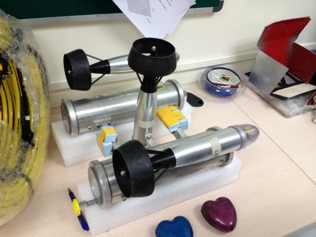
One of the AUVs.
[1.1] The Competition
The Singapore AUV Challenge 2013 was the most recent competition that our AUV participated in. The project was passed down to us just after the competition.(We got fourth!) Our AUV did not manage to make it through the gate and the motion of the robot was also very choppy.
The video of the competition can be found here:
[1.2] Getting Down To Business
Why do we need the Arduino Pilot Mega? Well, we need a compass sensor! If you saw that video above, you would know that our AUV turned around and went back the start point. This was because it did not have a sensor to read it's orientation.
Here are some useful links to get you started:
Camera Compatibility ----> http://elinux.org/RPi_VerifiedPeripherals#USB_Webcams
Python Programming ------> http://www.codecademy.com/tracks/python
Basic Image Processing --> http://www.cl.cam.ac.uk/projects/raspberrypi/tutorials/robot/image_processing/
Blob Detection ---------------> http://www.cl.cam.ac.uk/projects/raspberrypi/tutorials/robot/blob_detection/
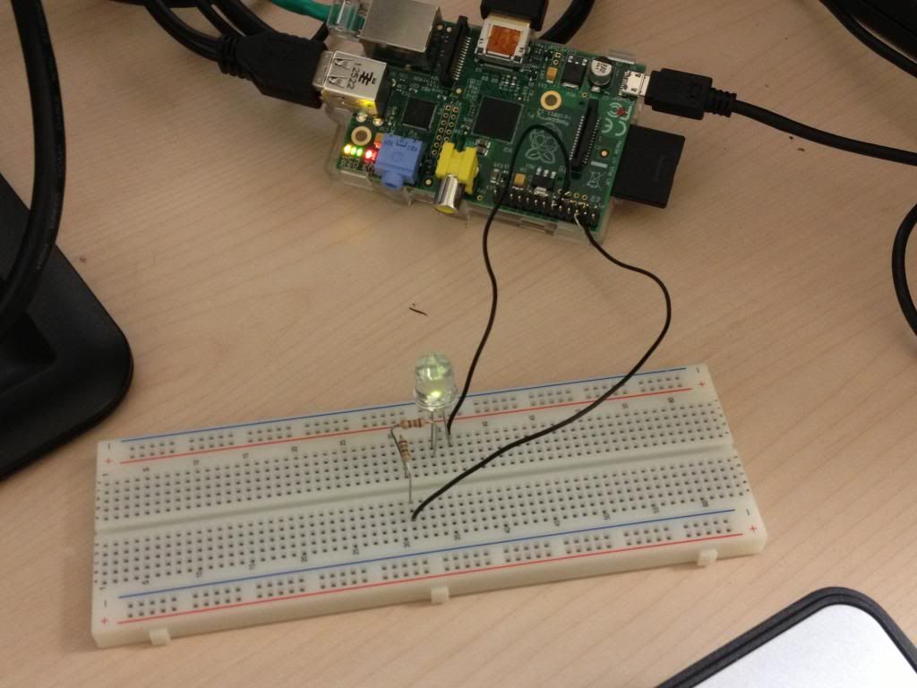
Not as easy as you think.
[1.3] Pool Day!
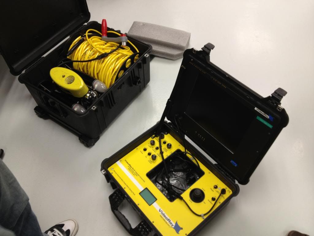
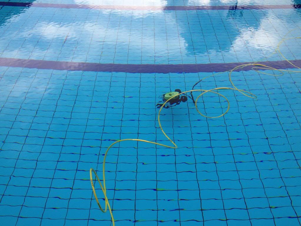
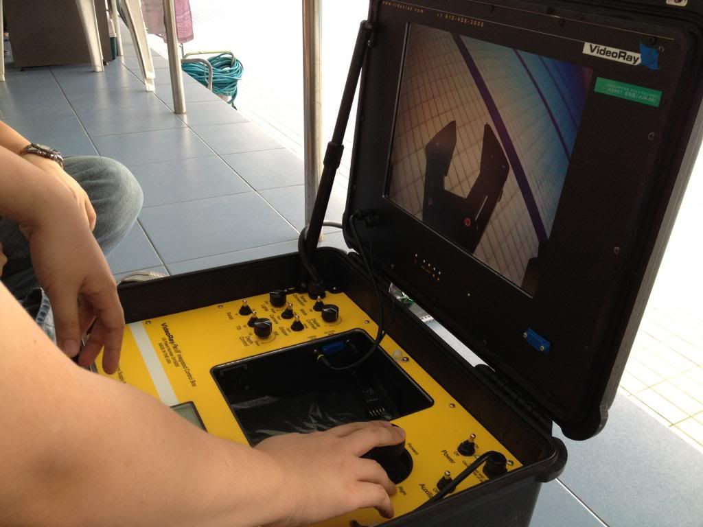
No, no one is swimming. Only the Remotely Operated Vehicle(ROV) is swimming. Our supervisors brought us down to pool to demonstrate the ROV. Everyone from all the groups was present and we sure had fun.
[The Nuclear Briefcase. Press to launch.]
[In you go!~]
[The vision is cool right?!]
[2.0] Becoming a Keyboard Warrior

Before you start reading this, please ensure that you are at least familiar with Linux commands as well as Python Programming, else you wont fully understand what i will be typing here.
Whether you are using a Raspberry Pi or BeagleBone, the first step that i recommend you do is to familiarize yourself with the board. If you are using the Raspberry Pi, you need to have an OS flashed into an SD card.(We used Raspbian Wheezy) And so here is a guide on the pure basics of operating your embedded system.
{Starting up the Raspberry Pi}
1.) Connect your Pi to a power outlet.(5V,1A Don't turn it on yet!)
2.) Connect the rest of the necessary peripherals.(E.g. Mouse, Keyboard, Screen)
3.) Power on the Pi and wait for it to prompt you for your login and password.(Default login is pi, Default password is raspberry)
4.) If this is the very first time you are setting up the Pi, type in sudo raspi-config to configure your Pi.(Use the arrow keys to control the UI)
5.) Type in startx. This code is to launch the GUI desktop.($60 mini computer. Cool right?)
6.) You can access the terminal again by double clicking on the LXTerminal icon on the desktop.
7.) Type in sudo shutdown -h now to shutdown your Pi.
Congratualations! You have learnt to start up, configure and shutdown the Raspberry Pi. (Which is equivalent to learning how to shutdown and startup the PC you are using to view this now.)
[2.1] Your First Code!
This is where the real fun begins! There are a few things you need to take note of first though. On your GUI, there should be 2 icons, IDLE and IDLE 3. What's the difference? IDLE operates on Python V2.7 while IDLE 3 operates on Python V3.2. The difference between these two versions of Python can be found here.
I'd recommend using Python V2.7 because alot of essential libraries are available there. Not all of them have been ported over to Python V3.2 yet. And so here begins the tutorial.~
{Typing and Running your First Code}
1.) Run IDLE or IDLE 3. The Python Shell window will appear.
2.) Click File -> New Window.
3.) Write your code on the new window.
4.) To save your file. File -> Save As -> "filename".py (remember to add .py at the end so the system will recognise as a python file)
5.) On the code window click Run -> Run Module. Your code will run on the Python Shell window.
Have fun playing around!
[2.2] GitHub
What is Github? Github is a very very useful tool for you to install on your embedded system. This is because it serves as a backup for your codes. An exmaple would be what you are looking at now. This website is hosted by github pages and if you scroll up and click the "View on GitHub" link, you will see all the codes for GPIO testing, Computer Vision, etc that i have left for you.
A detailed tutorial on how to install and use GitHub can be found here.
[2.3] Blinking Some LEDs
This will be the first time you will be using your embedded system to control elements in the outside world. It may be confusing trying to do it the first time round so i'll try to make this as precise and simple as possible.
Firstly, you are going to need to have a few things besides your embedded system.
Seem familiar?
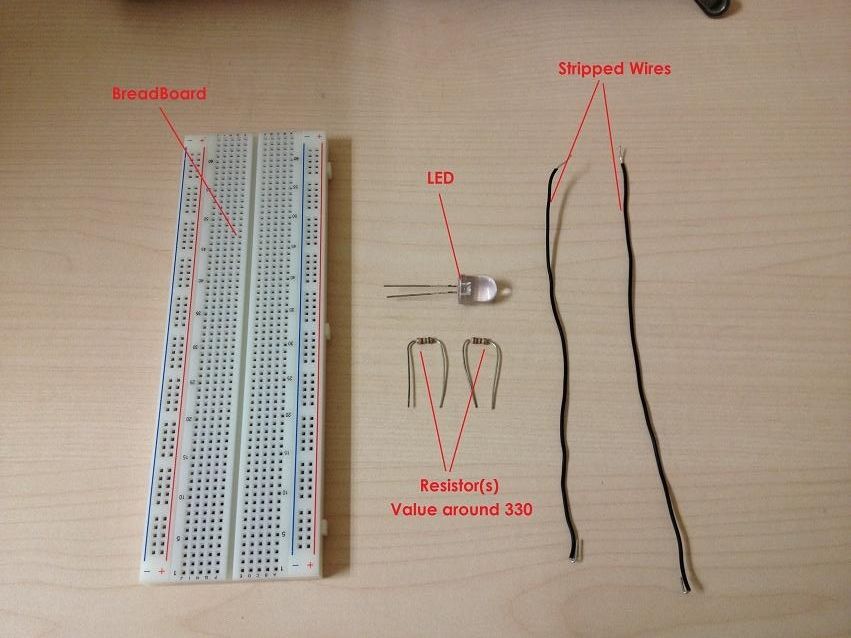
Connect it up!
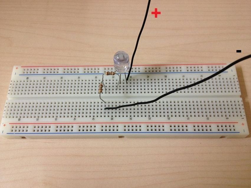
Done with the hardware side? Now it's time for the software side. For the Raspberry Pi, you need to import in some new libraries in order to utilize the GPIO pins. Dont worry, it's not rocket science. Ensure that your internet on the Pi is working before you type in the codes below.
Type in these codes on the LXTerminal of your Pi:
sudo apt-get update && sudo apt-get upgrade
sudo apt-get install python-dev
sudo apt-get install python-rpi.gpio
Congratualations! You are done configuring your Pi to use it's GPIO pins. You can get the source code to blink an LED in the repository. ("GPIOtest") Make sure you understand the code!
Pin Diagram Allocations
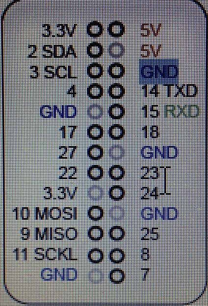
In your program, let's say you assign pin 11 to be an output pin. That pin you programmed will be GPIO no. 17. This is because pin 1 is the GPIO 3.3v, pin 2 is the GPIO 5v, pin 3 is the GPIO 2SDA, pin 4 is the GPIO 5V, etc...
Ensure that when you connect up the wires of your LED test kit to your Pi, do NOT short circuit any of the pins together. (It could damage the board)
Hmm? The program in the repository has an error message when you run it in the python shell? That's because you need to run the program as a root user!
Open your LXTerminal and type these in:
cd /home/pi/"Just list the directory path to where you saved the .py program to"
sudo python GPIOtest.py
If you still need more documentation, you can find it here.
[2.4] Enabling I2C and SPI
So you have configured your Pi, blinked some LEDs and have a clear vision as to what needs to be done? Nice work!
Before we can start to use external devices such as webcams or even another Arduino board, it is important to enable I2C and SPI protocols. What are they? I2C stands for Inter Integrated Circuit Communications while SPI stands for Serial-Peripheral-Interface. They are both communication protocols that allow a microcomputer to link to other micros or integrated circuits. Unfortunately, these protocols are blacklisted on the Raspberry Pi by default so we will need to fix that.
Getting rid of the Blacklist:
Type in these codes on the LXTerminal of your Pi:
sudo nano /etc/modprobe.d/raspi-blacklist.conf
(Add a # in front of both the blacklisted lines)
(Save and exit file)
Enable I2C
Type in these codes on the LXTerminal of your Pi:
sudo nano /etc/modules
(Add in i2c-dev below the last line)
(Save and exit file)
(Reboot Pi)
Installing I2C tools:
Type in these codes on the LXTerminal of your Pi:
sudo apt-get update
sudo apt-get install i2c-tools
[2.5] Using a Wireless Network Adapter
*This section is optional*
There are a few ways to get a working Internet connection on the Raspberry Pi. Today, i will only be sharing 2 of the most commonly used ways.
The first way is the simplest of them all. Just use an Ethernet cable and plug one end into a modem and the other into your Pi's ethernet port. Mission complete!! *If the connection doesnt seem to work, unplug the ethernet cable and wait for 20 seconds before trying again*
The second way is slightly more complicated and it is the main topic for this section. Using a Wireless Network Adapter. Some Wireless Network Adapters will require you to use a powered USB hub if the power consumption of the adapter is too high. This was the setup i used:
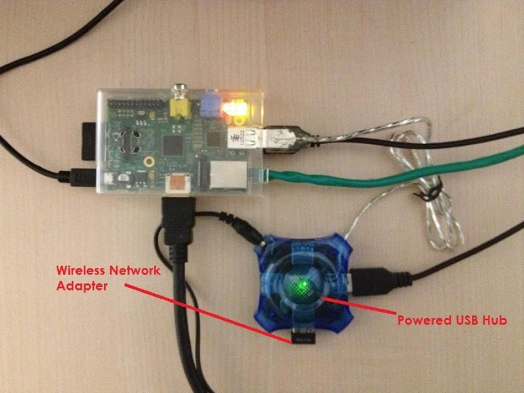
As you can see, the Wireless Network Adapter is connected to a powered USB hub. In the pictue below, you can see the results of plugging the Wireless Network Adapter. A description of each window is given below as well.
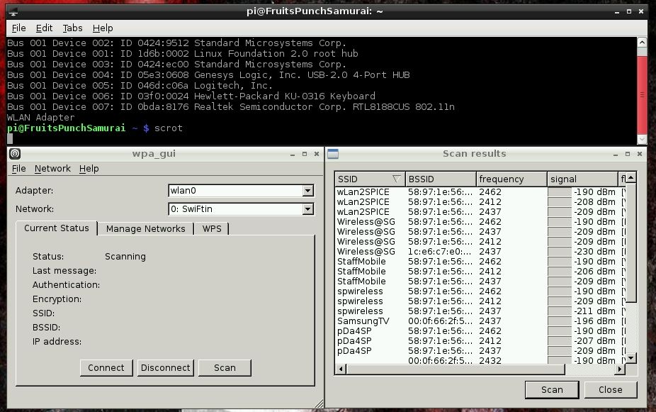
Topmost Window: This window shows that the Raspberry Pi detects the Wireless Network Adapter as "Realtek Semiconductor Corp. RTL8188CUS 802.11n WLAN Adapter.
Bottom Left Window: This window shows that the Raspberry Pi WiFi configuration software detects the Wireless Network Adapter as WLAN0.
Bottom Right Window: This window shows that the Wireless Network Adapter is able to scan for networks.
[2.6] Beauty is in the Pi of the Beholder
Hey there! Be sure to customize your Pi however you see fit! There are a ton of ways to customise your Pi and i think it will be a good idea to invest some time into it since you will be with it for some period of time.
Yeaaaaaaaaaa...!
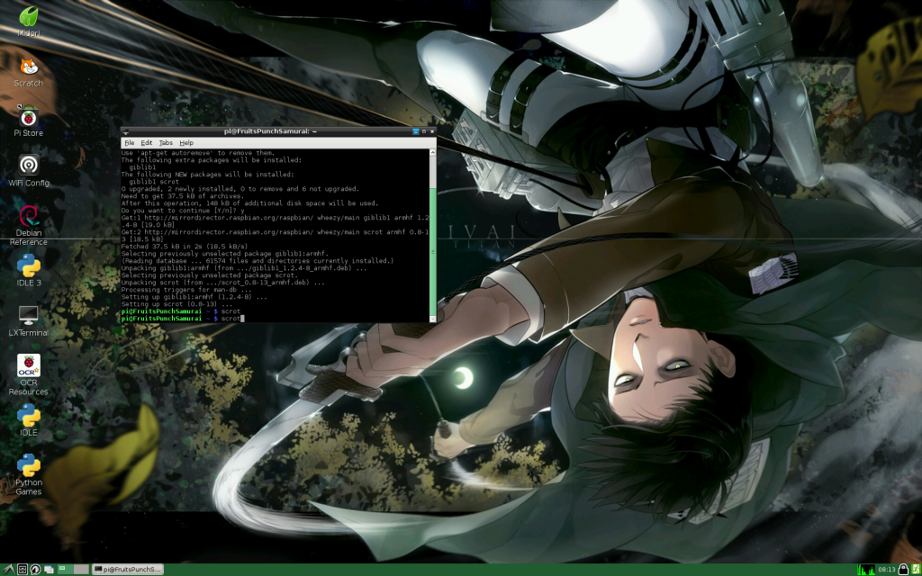
Looks nice? No?
So you're probably wondering how to take screenshots. You can do this by installing a program called "Scrot". With scrot you can take screenshots. This will be handy for picture documentation like i was doing.
Type in these codes on the LXTerminal of your Pi:
sudo apt-get install scrot
(Type in scrot in terminal to get a screenshot)
Have fun!!
[3.0] Interfacing Via USB
We have managed to interface the Raspberry Pi with the Arduino Pilot Mega V2.5 Via USB connection. We mainly got our information from "Getting Started with Raspberry Pi" from Matt Richardson and Shawn Wallace. The process of how we did it will be explained here.
First, we need to install Arduino into Raspbian.
Type in these codes on the LXTerminal of your Pi:
sudo apt-get update
sudo apt-get install arduino
Next, in order to get the Raspberry Pi to communicate with the Arduino via serial port, we need to make sure that the pi user has permission to do so.
Type in these codes on the LXTerminal of your Pi:
sudo usermod -a -G tty pi
sudo usermod -a -G dialout pi
Congratulations and salutations! The Raspberry Pi should be able to recognise the Arduino Pilot Mega V2.5 now. Type lsusb into the LXTerminal just to verify. You should see this:

See the Arduino SA Mega 2560? Yeaaaaaa
Now let's test out the connection! Open up your Arduino IDE on the Raspberry Pi. There are two things we need to do before we can start coding. First, click on (Tools -> Board) and select the Arduino Mega 2560. Next, click on (Tools -> Serial Port) and there select /dev/ttyACM0. You have just successfully configured the Arduino IDE to recognise the Arduino Pilot Mega V2.5. Thus, you can start uploading codes into the APM itself!
[3.1] Return to Sender
Alright so if we want to communicate over a serial connection, we need to import in the serial libaries into the Raspberry Pi!
Type in these codes on the LXTerminal of your Pi:
sudo apt-get install python-serial python3-serial
Now, open up your Arduino IDE and upload this code to the board.
Type in these codes on the Arduino IDE of your Pi:
void setup()
{
Serial.begin(9600);
}

void loop()
{
for (byte n = 0; n < 255; n++)
{
Serial.write(n);
delay(50);
}
Now, open up your IDLE and run the python script through the LXTerminal as sudo
Type in these codes on IDLE:
import serial

port = "/dev/ttyACM0"
serialFromArduino = serial.Serial(port,9600)
serialFromArduino.flushInput()
while True:
    if (serialFromArduino.inWaiting() > 0):
        input = serialFromArduino.read(1)
        print (ord(input))
[3.2] Compass Sensor Readings
With alot of help from our Technical Support Officer, Jacqueline, we managed to get the Arduino Pilot Mega V2.5 to output the compass sensor heading values to the Arduino IDE's serial monitor. This was done by getting the source code which you can download from here. For detailed instructions on how to use the code, please refer to here.
After successful compiling and uploading to the Arduino Pilot Mega, we monitored the results using RealTerm. However, the data we got was useless. We got random numbers printed all over the terminal.
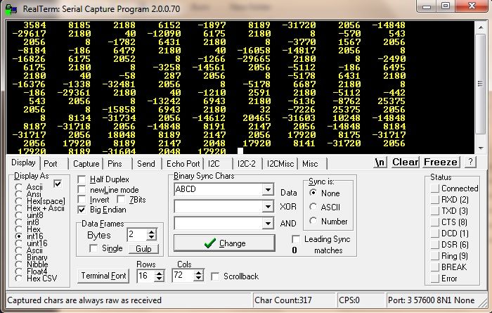
See? Alien Language. Jacqueline then helped us with identifying and troubleshooting some of the examples found in the libraries. We found a suitable example in YourArduinoSketchbook > libraries > AP_Compass > examples > AP_Compass_Test. Open up the .PDE file with your custom Arduino IDE and upload it to the Arduino Pilot Mega.

So you're probably having trouble understanding how to interpet the compass sensor readings. I'll explain it here.
North is indicated by 0.00 Degrees by the compass sensor. East is -90.00 Degrees. West is 90 Degrees. South is 180/-180 Degrees. Starting to see a pattern? Yes, this compass does not output 0-360 degrees. Instead when you rotate it clockwise, the readings go negative and vice versa. If you still can't understand, test out the Arduino Code in the repository!
[3.3] The Finale
Now, you know how to interpret the compass readings and you've probably seen the code running. Now, it's time to send the data to the Raspberry Pi instead of your PC. Sounds complicated? Nah not really, i'll break it down for you.
First off, i'll highlight some important stuff to you. Take a look at the Arduino Code and the Raspberry Pi Code in the repository. The Arduino Code extracts the compass sensor heading data and sends it to Serial port 0. Which is the USB port. The Raspberry Pi Code receives this data from /dev/ttyACM0, which is also it's USB port. Starting to make sense? Also, make sure that the Arduino board is transmitting data at the SAME BAUD RATE as the receving of data of the Raspberry Pi. The baud rate is currently set to 115200.
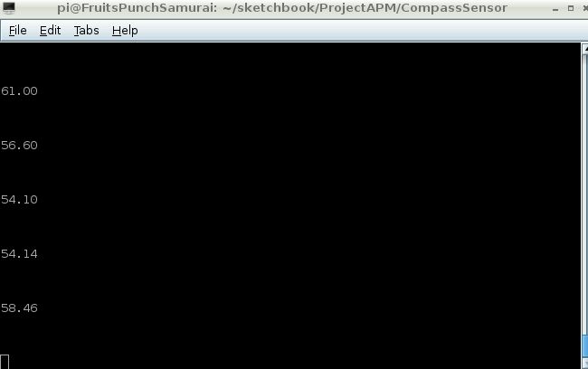
Upload the Arduino Code into the Arduino Pilot Mega V2.5 and plug it into the Raspberry Pi. Then run the Raspberry Pi code as sudo. You should get the result above! Do take note that the program will write the compass heading data to a text file just beside the CompassSensor.py file.~
[4.0] Testing the Program
It's time to test out the program! Hopefully, it can detect black underwater!
This was the setup i used for testing:
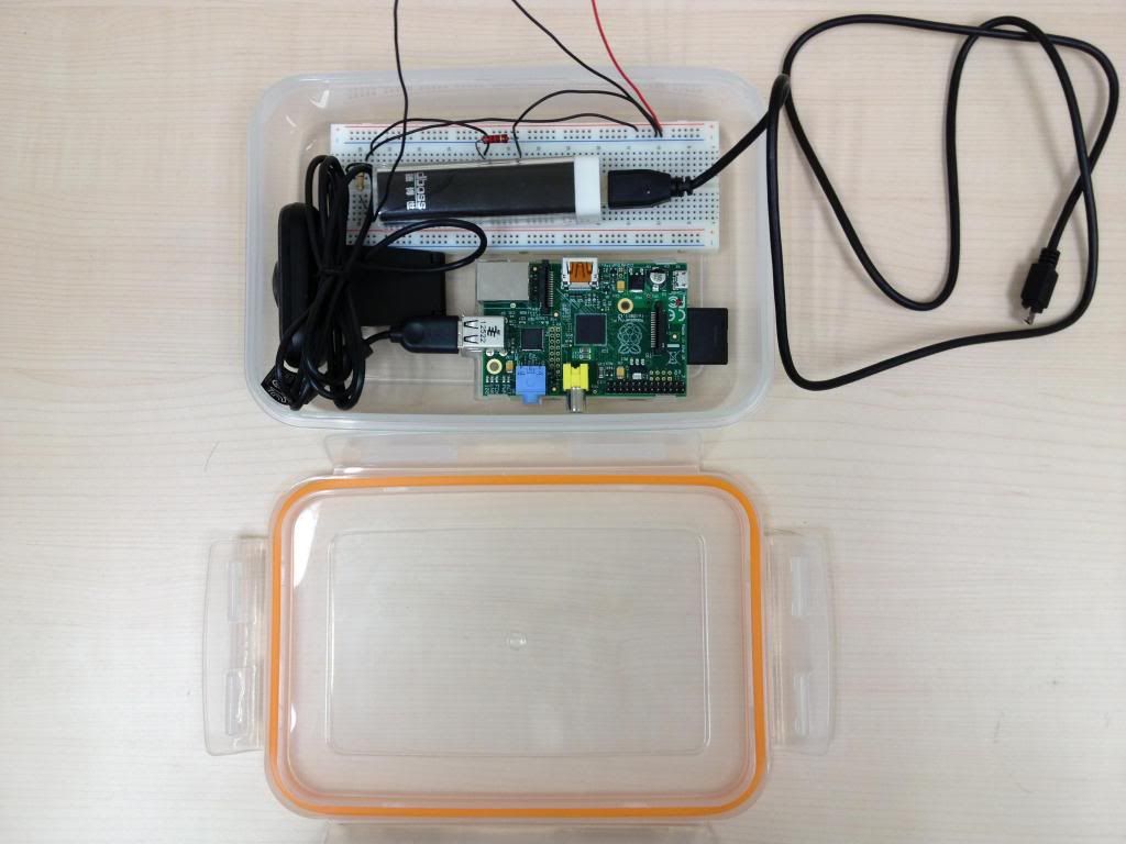
The setup basically consists of a watertight box fitted with the Raspberry Pi, 5V 1A Battery Pack and a temporary circuit for a magnetic switch.
There will be a continous stream of processed video stream. However when a magnet is brought near the magnetic switch, the contacts will close and the Raspberry Pi will capture two .jpg images from the video feed. The only thing holding me back now is the ridiculous 371 PSI haze...
The haze reached a high of 401 PSI! And the N95 masks are all sold out! And Singaporeans are still queuing for Hello Kitties! Ok back to work.
We have changed the design of our testing kit due to one major reason. There wasn't enough space (it was intended for computer vision callibration only). We changed it to a bigger LocknLock box as shown below.
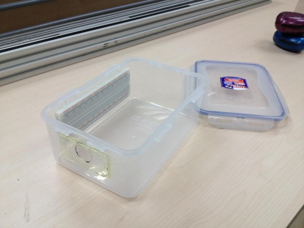
As you can see, we have made two major modifications to the box. Firstly, we have made a hole at the side of the box and resealed it with a piece of transparent acrylic and epoxy that smells like dead fish. This is so that our computer vision will not be hindered underwater.(The box is slightly translucent) The second modification is that we have attached a breadboard at the side of the box for our circuitry. We have tested the box for it's "waterproof-ness" at the SP swimming pool, for 10 mins at 2m depth. No leakages!
We have also managed to fit all that we need inside the box as shown below.
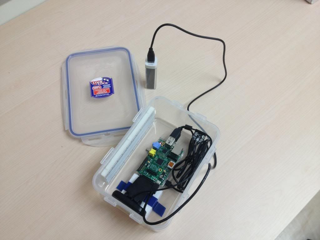
We have written a program known as run.py that basically provides a simple user interface that gives access to all the test programs. (yellowtest,blacktest,compasssensor)The program will prompt you to select the testing program you wish to execute. Then it will wait for a input from the magnetic sensor before it executes the selected program. A blue LED will be lit the moment the program executes.
[4.1] Pool Testing
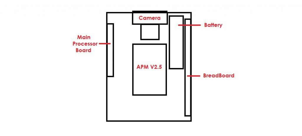
We have also reorganised the components within the box in such a way where you will not need to retrieve the components to recalibrate them. The placement of components is as shown below.
The pool testing was a success. (After trying twice) We managed to calibrate our two blob detection programs to detect both yellow and black underwater. We also tested the compass sensor. How did we test it? Well Brian just kept spinning underwater while the sensor's data was logged on the Raspberry Pi
Here is a video of our pool testing process: